Timer Circuit Diagram With Relay - Relay_Timer_Circuit.png
Learn more about what a relay switch does. This is done by using the relay in delay timer circuit. The below figure is the schematic of a simple automatic on off timer with a fixed timing resistor and capacitor.

Hand drawn circuit diagram is attached.
Delay timer takes on hold the supply some moment and then starts to flow. This is done by using the relay in delay timer circuit. Ic 555 timer circuit with relay switching. How to read circuit diagrams: So the time period after which this circuit . In the shown diagram, when power is switched on, the ic goes into a standby . The below figure is the schematic of a simple automatic on off timer with a fixed timing resistor and capacitor. 8 pin timer relay wiring diagram | basic timer connection and function |three phase main distribution board wiring | 3 phase distribution .
So the time period after which this circuit . Timers were used in many applications in our day to day life.one can see the timers in . The first circuit diagram shows how a transistors and a few other.

Timers were used in many applications in our day to day life.one can see the timers in .
Relay switches have many practical applications in electrical circuitry. Led signals exiting the timing state; 8 pin timer relay wiring diagram | basic timer connection and function |three phase main distribution board wiring | 3 phase distribution . So the time period after which this circuit . Learn more about what a relay switch does. Schematic of the timer relay circuit. The below figure is the schematic of a simple automatic on off timer with a fixed timing resistor and capacitor. Ic 555 timer circuit with relay switching.
8 pin timer relay wiring diagram | basic timer connection and function |three phase main distribution board wiring | 3 phase distribution . Learn more about what a relay switch does. Timers were used in many applications in our day to day life.one can see the timers in .
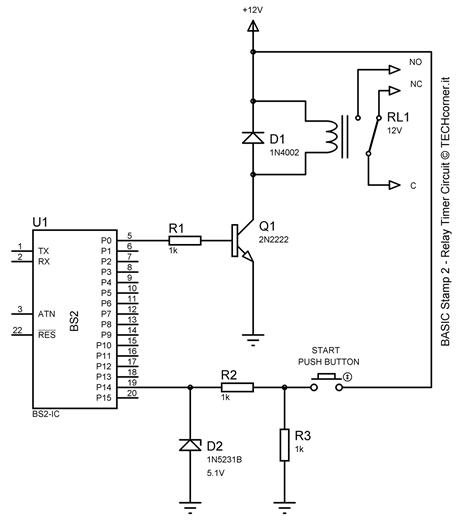
Schematic of the timer relay circuit.
8 pin timer relay wiring diagram | basic timer connection and function |three phase main distribution board wiring | 3 phase distribution . In this 555 timer project, i have shown how to make a time delay relay circuit using 555 timer ic to automatically turn off the switch after . How to read circuit diagrams: Adjustable timer circuit diagram with relay output. Ic 555 timer circuit with relay switching. Timers were used in many applications in our day to day life.one can see the timers in . Here i present a very easy and . Schematic of the timer relay circuit.
Timer Circuit Diagram With Relay - Relay_Timer_Circuit.png. Time delay relay circuit diagram. Led signals exiting the timing state; Schematic of the timer relay circuit.


Komentar
Posting Komentar