Gfci Outlet Wiring Diagram : Bathroom wiring diagram | Home electrical wiring, Bathroom
This diagram illustrates the wiring for a circuit with 2 gfci receptacles followed by a light and switch. In this gfci outlet wiring and installation diagram, the combo (switch + outlet), spst (single way) switch and ordinary outlet is connected to the load side of gfci. The diagram below shows the power entering the circuit at the grounded outlet box location, then sending power up to the switch and a switched leg back down to the outlet. Gfci combo switch and outlet wiring circuit diagrams and installation. Mar 11, 2021 · below mentioned wiring diagram shows a single gfci outlet connected with the multiple outlets.

Wiring gfci outlets on one circuit.
In this diagram, the switch built into the combo device is wired to control the gfci outlet itself. Wiring diagram for a switched gfci combo outlet. The toggle switch in the combo switch outlet controls the first light bulb while the single way. The source neutral is connected the line neutral terminal. Feb 07, 2020 · wiring a gfci outlet may vary slightly from manufacturer to manufacturer, but for the most part, they follow the same general principles. The source hot wire is spliced with one of the switch wires and the other switch wire is connected to the hot line terminal on the device. We asked our pros to help us show new hires or even diyers how to do it properly. It means, all the connected loads to the load terminals of gfci are protected. 7) all supply wires must be copper and rated at a minimum 194°f (90°c). This diagram illustrates the wiring for a circuit with 2 gfci receptacles followed by a light and switch. By connecting the switch to the load terminals on the last gfci, the switch and light are protected against ground faults as well. The diagram below shows the power entering the circuit at the grounded outlet box location, then sending power up to the switch and a switched leg back down to the outlet. Look for a crossover cable color code with a wiring diagram for rj45 crossover cable or cross cable is a type of ethernet cable that is used to connect similar types of networking devices, in contrast to straight through cable which is used to connect different devices.
7) all supply wires must be copper and rated at a minimum 194°f (90°c). Wiring gfci outlets on one circuit. Wiring diagram for a switched gfci combo outlet. You should understand the basics of how to correctly add a new gfci outlet or replace an existing outlet with a gfci. This diagram illustrates the wiring for a circuit with 2 gfci receptacles followed by a light and switch.
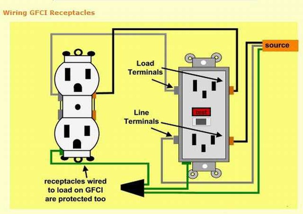
In this gfci outlet wiring and installation diagram, the combo (switch + outlet), spst (single way) switch and ordinary outlet is connected to the load side of gfci.
Mar 11, 2021 · below mentioned wiring diagram shows a single gfci outlet connected with the multiple outlets. Look for a crossover cable color code with a wiring diagram for rj45 crossover cable or cross cable is a type of ethernet cable that is used to connect similar types of networking devices, in contrast to straight through cable which is used to connect different devices. Feb 07, 2020 · wiring a gfci outlet may vary slightly from manufacturer to manufacturer, but for the most part, they follow the same general principles. 7) all supply wires must be copper and rated at a minimum 194°f (90°c). Gfci outlet wiring to protected a light. The source hot wire is spliced with one of the switch wires and the other switch wire is connected to the hot line terminal on the device. In this gfci outlet wiring and installation diagram, the combo (switch + outlet), spst (single way) switch and ordinary outlet is connected to the load side of gfci. Outlet wiring for a table lamp or a floor light fixture. The source neutral is connected the line neutral terminal. You should understand the basics of how to correctly add a new gfci outlet or replace an existing outlet with a gfci. As discussed before, gfci also known as ground fault circuit interrupter is a protection device against electric shock which detects the ground faults and leakage currents especially in outdoor and watery areas such as bathroom, kitchen, laundry etc. For instance, you need cross cable if you are connecting. Wiring diagram for a switched gfci combo outlet.
Gfci combo switch and outlet wiring circuit diagrams and installation. By connecting the switch to the load terminals on the last gfci, the switch and light are protected against ground faults as well. Gfci outlet wiring to protected a light. Feb 07, 2020 · wiring a gfci outlet may vary slightly from manufacturer to manufacturer, but for the most part, they follow the same general principles. We asked our pros to help us show new hires or even diyers how to do it properly.

For instance, you need cross cable if you are connecting.
The diagram below shows the power entering the circuit at the grounded outlet box location, then sending power up to the switch and a switched leg back down to the outlet. It means, all the connected loads to the load terminals of gfci are protected. Gfci combo switch and outlet wiring circuit diagrams and installation. This diagram illustrates the wiring for a circuit with 2 gfci receptacles followed by a light and switch. 7) all supply wires must be copper and rated at a minimum 194°f (90°c). As discussed before, gfci also known as ground fault circuit interrupter is a protection device against electric shock which detects the ground faults and leakage currents especially in outdoor and watery areas such as bathroom, kitchen, laundry etc. You should understand the basics of how to correctly add a new gfci outlet or replace an existing outlet with a gfci. The toggle switch in the combo switch outlet controls the first light bulb while the single way. Wiring diagram for a switched gfci combo outlet. In this diagram, the switch built into the combo device is wired to control the gfci outlet itself. These electrical wiring diagrams show typical connections. For instance, you need cross cable if you are connecting. Mar 11, 2021 · below mentioned wiring diagram shows a single gfci outlet connected with the multiple outlets.
Gfci Outlet Wiring Diagram : Bathroom wiring diagram | Home electrical wiring, Bathroom. Wiring gfci outlets on one circuit. For instance, you need cross cable if you are connecting. It means, all the connected loads to the load terminals of gfci are protected. You should understand the basics of how to correctly add a new gfci outlet or replace an existing outlet with a gfci. When we are installing the gfci at the start of the line and the rest of the outlets are taken as load then we install only one gfci outlet per circuit.


Komentar
Posting Komentar